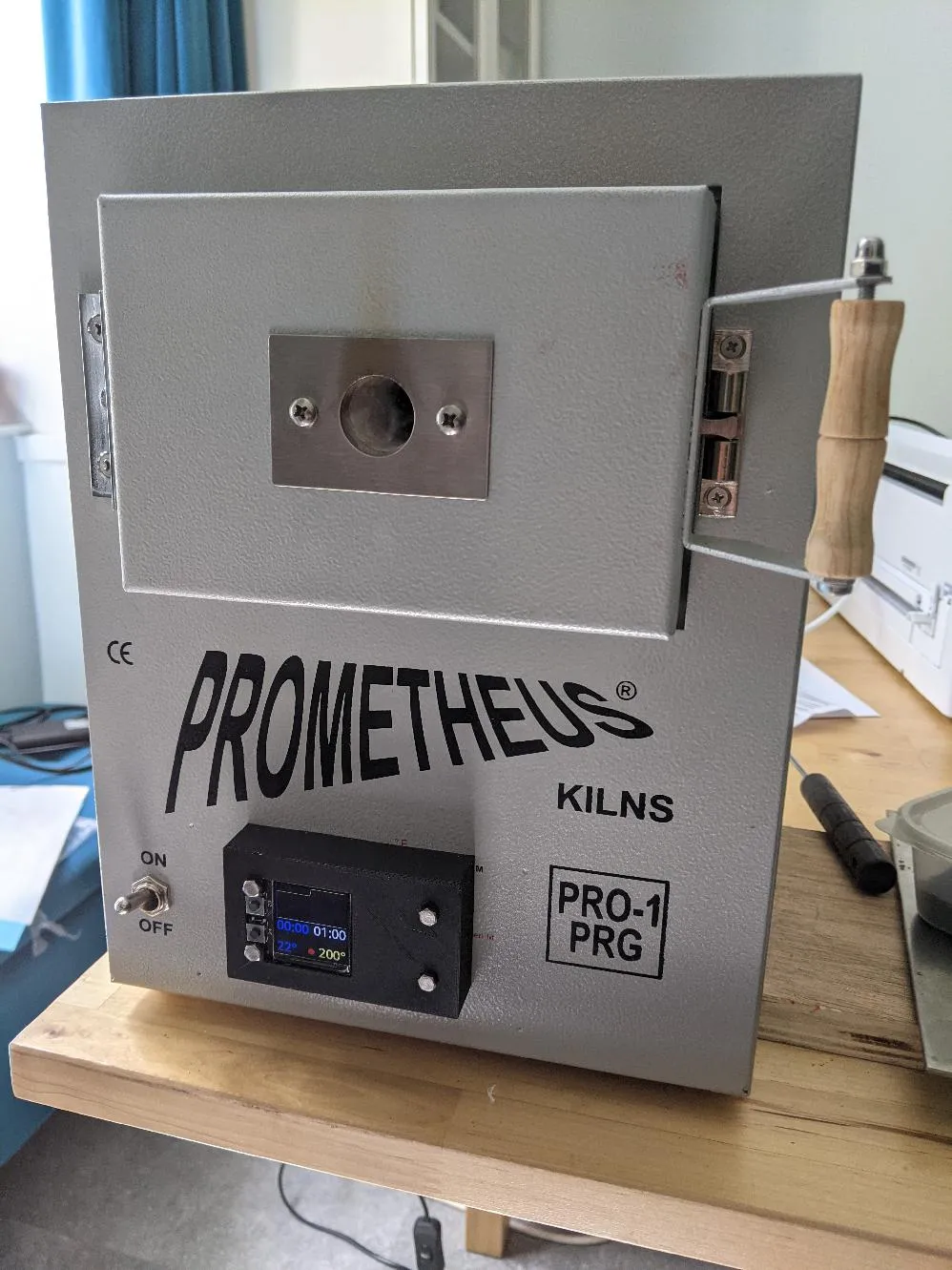
I have a small “Prometheus Pro-1 PRG” Jewellery kiln for experimentation and artwork. Its a programmable kiln, which allows you to have programmes with multiple cycles of heating and cooling over time, which is essential for glass fusing.
However, the user interface leaves something to be desired:
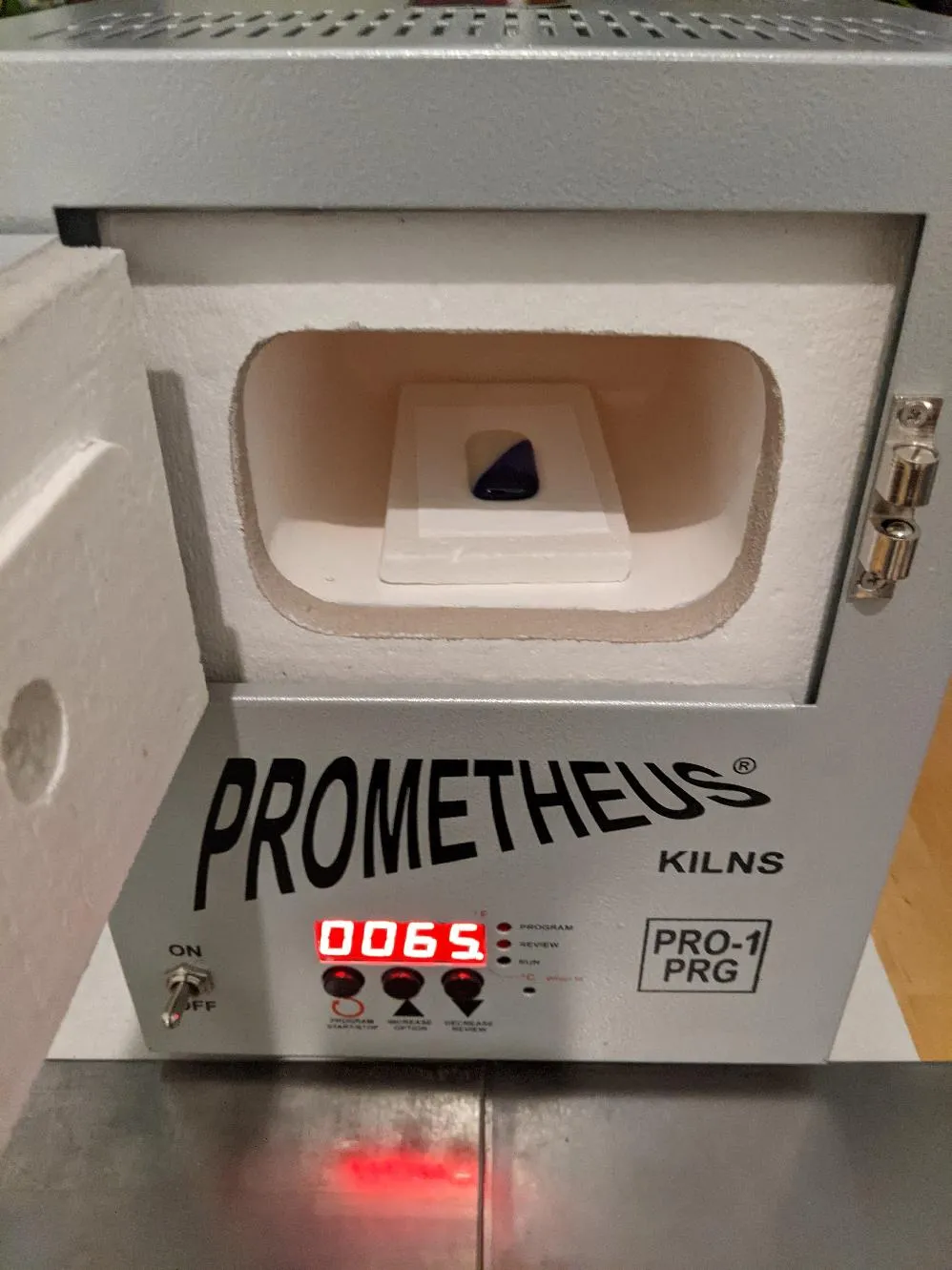
At the bottom you’ll see there’s a 4 digit LED display, three buttons, and some other holes on the right for some status LEDs. This is actually an OEM version of the “Orton Ramp/Hold controller”. Orton dominate the kiln controller market, and they have this quite limited three-buttons design. I see they are now trying touch screen controllers. However, they’re all extremely expensive.
Programming the kiln is done using those three buttons: it is not particularly fun. I found this was actively discouraging me from experimenting.
I was browsing around one night and stumbled across a github project: Jason Bruce’s Kiln Controller. This uses a raspberry pi as a cheap inexpensive kiln controller.
Sounds great! It needs a thermocouple to monitor the temperature and a solid state relay to control the kiln’s heater. My kiln already has both since the Orton controller uses them for the same purpose: I just need to replace the original controller.
Electronics Required
Jason gives an great overview and circuit diagram on his site.
However, here is what I used:
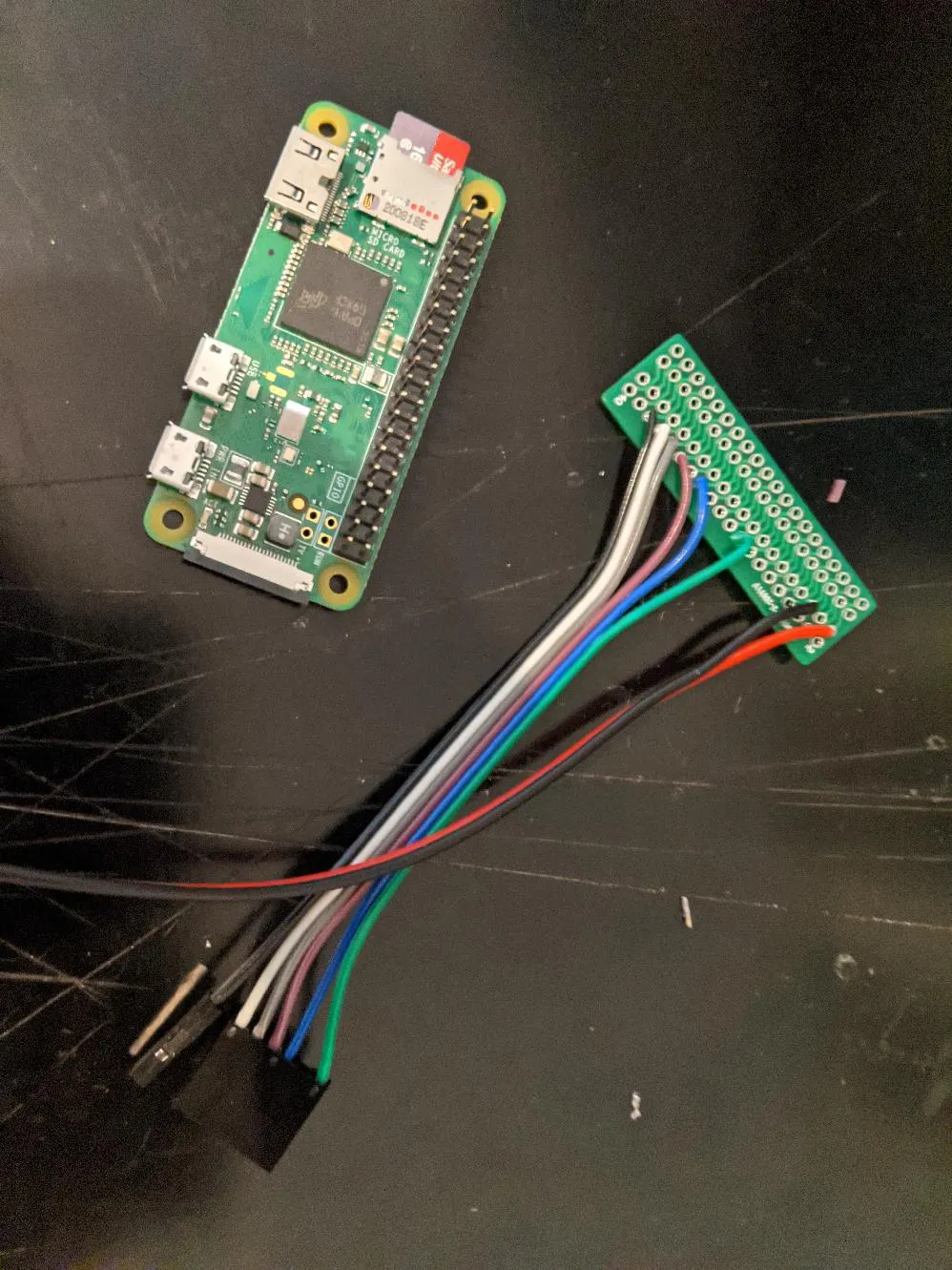
- Raspberry Pi Zero W - very cheap, very small, and has enough processing power for the job.
- Adafruit Mini PiTFT 1.3 - Although the kiln controller exposes a web interface, I wanted a display on my kiln as well.
Adafruit MAX31855 board - this reads the signal from the thermocouple and converts it into a temperature in C.- Adafruit MAX31856 board - this reads the signal from the thermocouple and converts it into a temperature in C. This is an update to the MAX31855; the MAX31855 works fine (with some software changes); I only got this so I could help support it.
- Generic Pi GPIO expansion board - I got one of these to make it easier to attach wires to the Pi’s GPIO lines.
- BC547 transistor - the raspberry pi can output a max of 3.3v from one of its GPIOs at relatively low power. However my solid state relay requires 5v with more power, so using a transistor to control it solves this issue (as described on Jason’s site).
Then, I started to put it together:
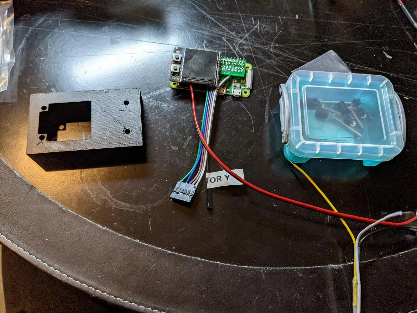
Enclosure
I wanted a neat case to hold the Pi, so I figured out a way to retrofit it into the existing case holes. Removing the original controller had left various gaps, so I designed a case which could use them:
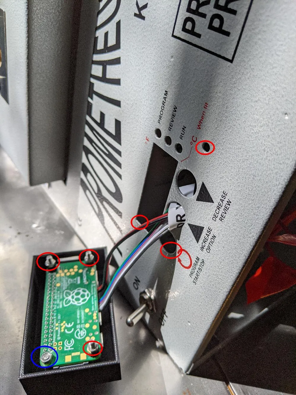
The red circled bolts fit into the red circled holes remaining from the Orton controller.
The blue bolt doesn’t have a matching case hole, so I cut it off short.
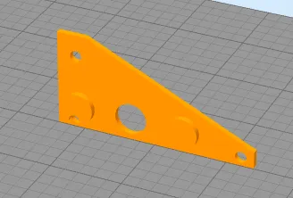
Finally, there’s a triangular plastic piece designed to live inside the case. It has some embossed circles which fit into the outer two button holes so it holds everything in place.
Internal wiring
Turning the kiln over to inspect its wiring…
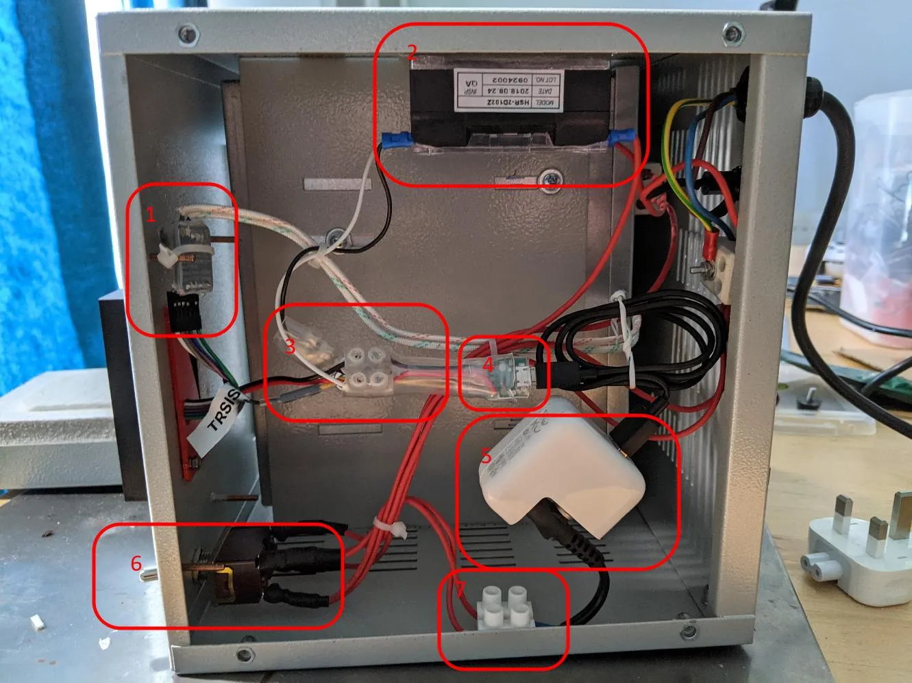
- MAX31856 board — you can see the two thick Type-K Thermocouple wires coming out of the top of it. I’ve covered this with heatshrink to avoid any shorts.
- Solid State Relay (as originally installed).
- DC power wiring — for powering the pi and the solid state relay. The BC547 is in here too. All safely heatshrinked.
- One of those little micro USB adapters (like I used for the Musical horn).
- An old Apple AC->DC power convertor I had lying around to give the 5V supply.
- The original power switch that came with the kiln.
- Screw terminal epoxied onto the case to allow me to connect the power convertor to the AC voltage.
Software
Yay, surely we must be done now! Well, actually, no. Getting the kiln software to work took several weeks.
I think one of the main issues is Jason’s project was designed for a Ceramics kiln; the typical use case for that is quite different from a small Jewellery kiln.
PID Controller
The first hurdle was to “tune” the PID controller in the kiln controller software. I knew nothing about them, so I had to spend some time researching.
A PID controller starts for “Proportional, Integral, Derivative Controller”. They’re really common in industry and have a wide variety of uses, from controlling a relatively slowly-changing temperature system (like a kiln), to a very fast-moving robotic arm.
All uses have three tuned parameters, Kp, Ki, Kd, which operate on the error - the current difference between what we want and where we currently are.
They operate in a “PID cycle”: basically the pid controller regularly wakes up (in our case every 2 seconds), observes the error, and calculates an output number based on that error. This output number is then used to control the industrial system.
The output number is completely arbitrary: you need to convert it something the industrial system can understand.
In our case, the PID cycle is 2 seconds long, and works as follows:
- The PID controller calculates the output number based on the difference between our current temperature and the desired temperature (known as set point).
- It clamps this number between 0 -> 100 and divides it by 100, yielding a number between 0 and 1.
- It calculates heating_time = 2 (seconds) * number, and cooling time = 2 (seconds) * (1-number).
- It then heats/cools for those two times.
- It is now time for the next PID calculation, repeat!
You can read a pretty good explanation of general PID algorithm here.
Tuning a PID Controller
Tuning a PID controller basically consists of choosing the correct values of Kp, Ki, Kd to match your system. They will be unique to the exact instance of the system you are controlling.
The kiln-controller project documentation described a method for doing this, however, I found it did not work well for my kiln.
Cue much more research and playing with various online PID tuning systems.
In the end, I used the “classic” Ziegler Nichols methodology, as described in this very useful paper and this youtube video.
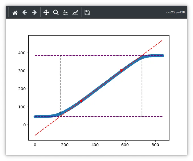
Basically, record the kiln’s temperature while you heat it up for a while, then stop heating. Finally, you use the gradient of the resulting curve, as well as the lag/overshoot to calculate starting values for the PID parameters.
Ziegler Nichols is really just a “rule of thumb” to get you started; it will very likely be not the most optimal set of values. But it’ll be in the right area. There are other more modern methods, but they were more complicated, and this worked for me.
I implemented an automatic kiln tuner in this merge request. It can output a chart to aid with the process:
Anti-Windup
During this process, it became obvious there was another problem with the software and my kiln: it suffered from windup.
The integral term in a PID controller is the sum of errors over time. My kiln takes a while to get from room temperature (~20C) to copper clay sintering temperatures (920C). As you can imagine, this means there will be a reasonably long time with a large error. This erroneously causes the integral term to become huge, leading to bad PID loop behaviour (it will massively overshoot the desired temperature).
In the industry, this is known as “windup”. You deal with it using “anti-windup”. There are various techniques to solve this, but the simplest is to simply not update the integral term if the error is too large. Jason has implemented this, but I found it didn’t quite work at 920C, so I’ve got a pull request queued with a possible fix.
Erroneous Thermocouple Errors
The next problem was my Thermocouple gives weird error reports once the kiln reaches ~900C. It randomly complains the Thermocouple is shorted to ground or to the supply voltage, neither of which was the case. However the actual temperature reading looked correct.
Some research turned up this forum thread. Basically that person figured out that above 900C, the air in the kiln turns into a plasma, which is slightly conductive. This slight conductivity appears to confuse the MAX31855 into reporting a problem when there is none.
Solution: ignore those errors with the MAX31855.
Interesting, the MAX31856 no longer reports those errors at all and does not suffer from the problem: I wonder if its a slight design flaw in the MAX31855?
I’ve implemented this fix (along with a number of others) in this pull request.
CSV Logging
To debug and work on this, I also implemented a Kiln logger to output data to CSV for analysis.
Kiln Display
Finally, I also built some kiln display software to make use of the TFT panel on my Pi. Although my panel has two buttons, they don’t do anything yet.
Here’s a picture of it in installed and in active use:
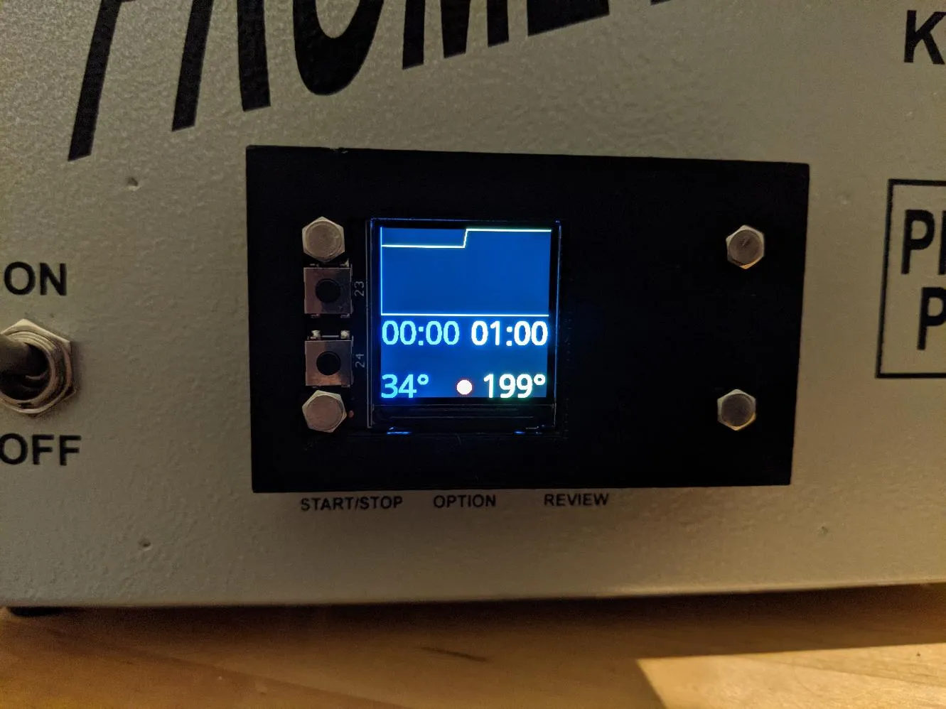
Once more there’s another pull request for it.
Wow, so many pull requests!
Yup, there are; I get the impression Jason is quite a busy person, so it may take a while for them to be reviewed.
In the meantime, I keep this branch up to date with all of them: ‘all’ branch in my repo.
Summary
This project took a while, and needed significant hardware and software modifications.
I almost gave up at one point through frustration. However, I’d just received my first Astra-Zenica vaccination, which made me spend a day relaxing on the couch. This removed my frustration so that I could push on to the end: an unexpected side benefit of Astra-Zenica!
The kiln is now so much better to use, the web GUI is a dream compared to the old controller:
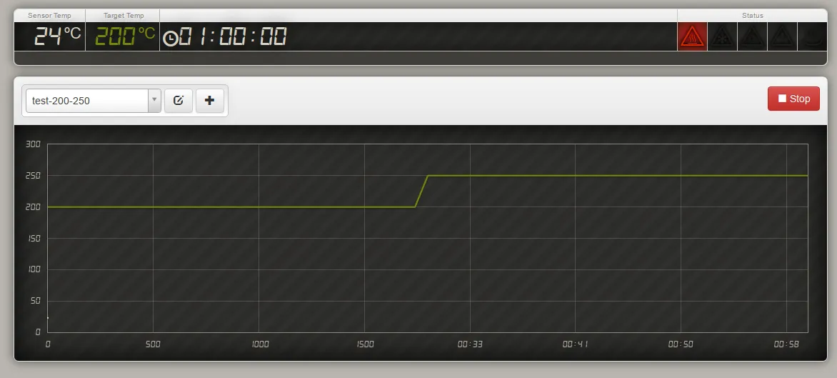
Now, on to doing things with the kiln!
2 Comments
giorgio antonio di donfrancesco ·
hi, i'm new with raspberry and python, tryed to give a look to this poject and followed all passages un bruce github, but when trying to start kiln-controller it says cannot import config.py file, may you help me!? thank you in advance
Enamelling Experiments – adq ·
[…] course, my upgraded kiln controller makes things an awful lot easier: I’m really looking forward to trying some glass with it […]