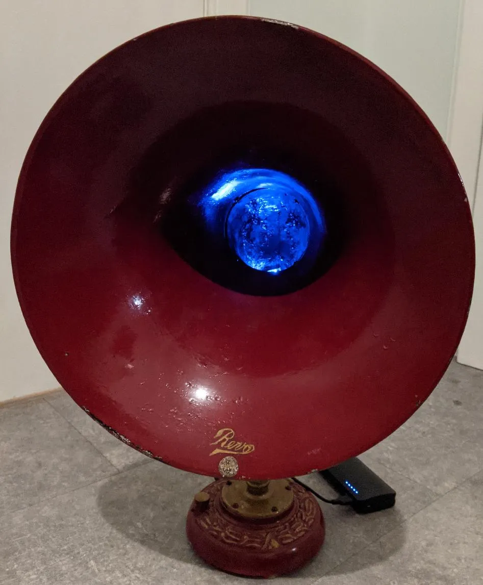
I inherited an old “Revo” speaker horn from my dad. I have a strong suspicion he acquired it from a “job lot” in an auction somewhere. He gave it the rather fetching red/gold/black paint job.
Anyway, its been in my flat looking kinda cool for ages: I wanted to make it even more cool :)
Internal Investigation
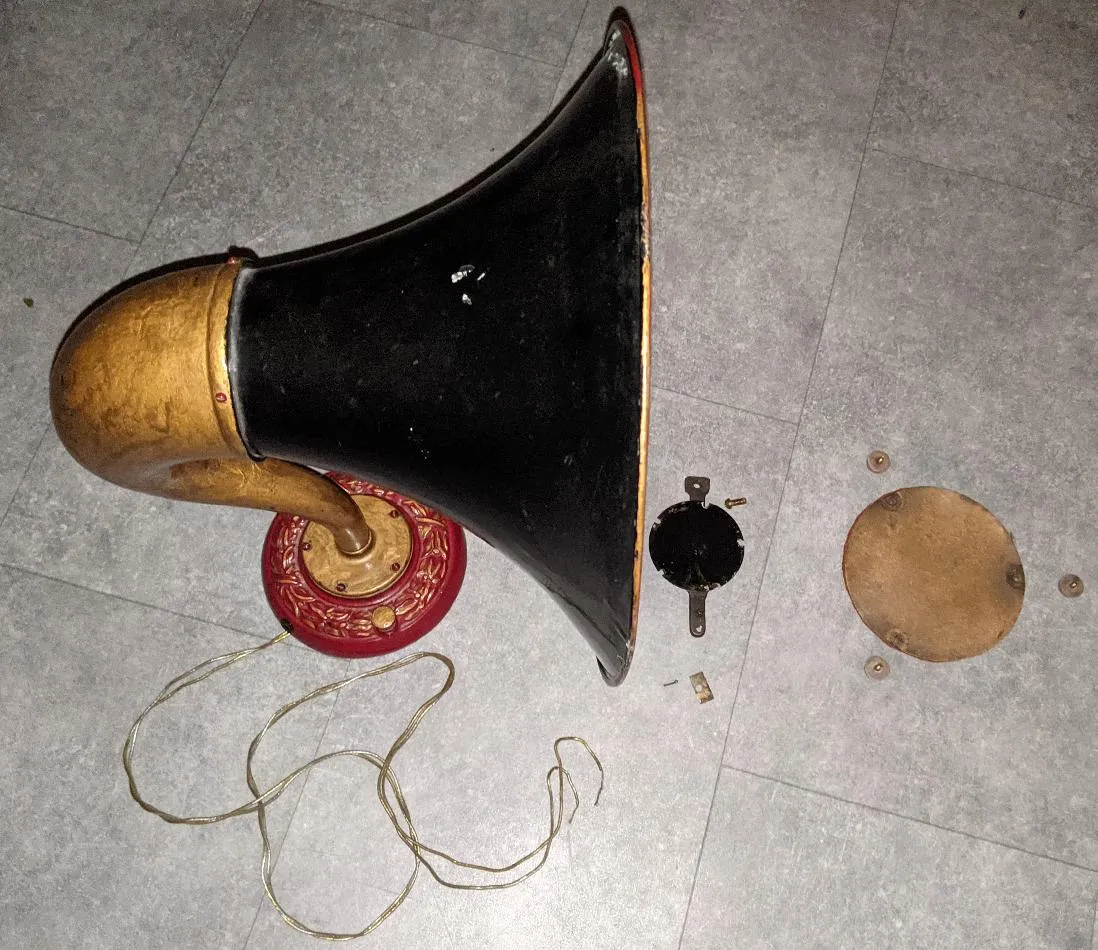
Opening it up revealed… a 1920/1930 speaker driver.
Of note:
- The wee black hole in the base where the original speaker wire is installed: this will become important later.
- The speaker driver unit.
- The original base of the horn protecting the driver and the three feet.
Speaker Driver Investigation
Looking closely it consists of two coils with ferrous cores (2), a permanent magnet (1) and a thin ferrous metal plate (3) mounted immediately above it.
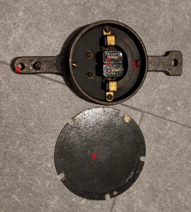
Oh, (4) is where the volume control screw goes.
As you play your AC signal through it, the coils will induce a magnetic field causing the metal plate to be - ah - “wiggled”, thus producing sound (though I can’t imagine it is great sound). The volume control screw changes the volume by literally changing the distance of the driver coils from the metal plate.
The big problem with this vintage equipment is that they have an impedance of thousands of Ohms, whereas modern speakers have quite low impedance (eg 8 Ohms). If you try and send sound from modern equipment to a vintage speaker driver, it’ll fry the driver coils.
I measured the DC resistance of the thing, and it was about 3600 Ohms.
The impedance is the resistance plus the effect of the coil/cores on an AC signal (effectively a speaker driver is an inductor); I couldn’t be bothered trying to measure/calculate that though as it will always be greater than the resistance.
Field Coils vs Permanent Magnet
Interestingly, this horn has a permanent magnet, which may date it to the 1930s.
One site I saw said that prior to the 1930s, permanent magnet tech was not very good, so equipment of this vintage used “field coils” instead: basically an electromagnet powered by a second set of connections.
However, another site mentioned they actually did use permanent magnets prior to field coils. Hum.
Oh well, whatever: I got on with doing stuff.
What Do I Need To Design?
I had two routes I could take:
- Try and build some sort of signal converter to match the impedance characteristics. I don’t have enough knowledge of AC electronics to do this without a lot more research, and the examples I could find were physically quite large.
- Replace it with something modern.
I chose option 2: I carefully removed the driver and stored it in case I ever wanted it.
Even though the innards are different, I want the horn to look exactly as it did before, but with a small contemporary hint: a micro USB socket (I decided not to use USB-C as that would just be too modern)
I needed to design the following:
- Custom replacement base plate to mount the electronics on.
- Custom USB socket to fit in the preexisting hole for speaker wire.
- Electronics (CPU board and speaker)
Later on, I added “blinky LED panel buried inside the horn itself” to this list because… Blinkenlights!
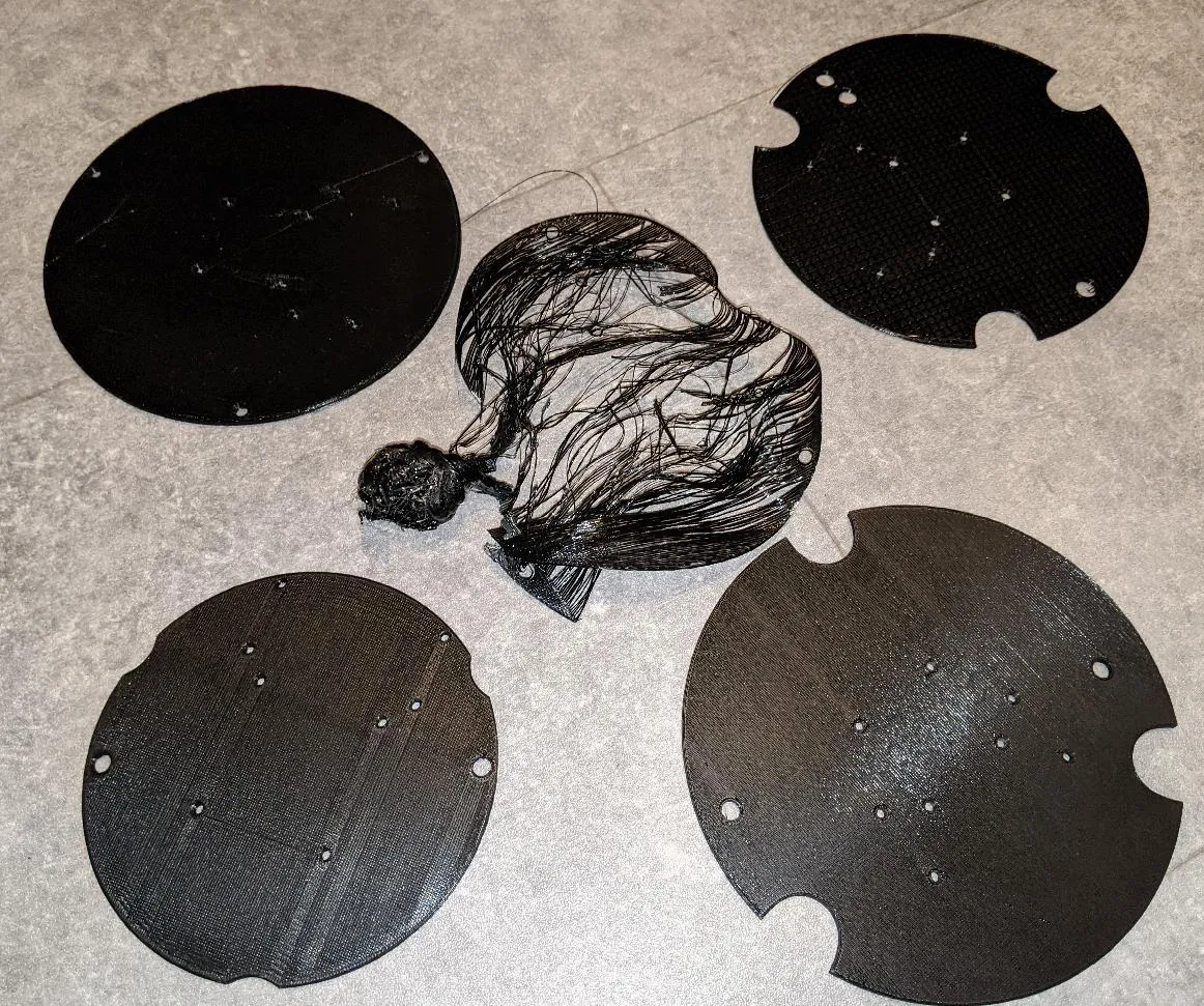
Design: Custom Mounting Plate
Retrofitting something into an existing unit is always quite fiddly: much measurement, design in Fusion 360, and test 3d prints (including one 3d printer meltdown when it all came unstuck and glued itself onto the hotend). You can see the design process as I gradually figured out how the replacement unit would work best.
Design: USB Socket
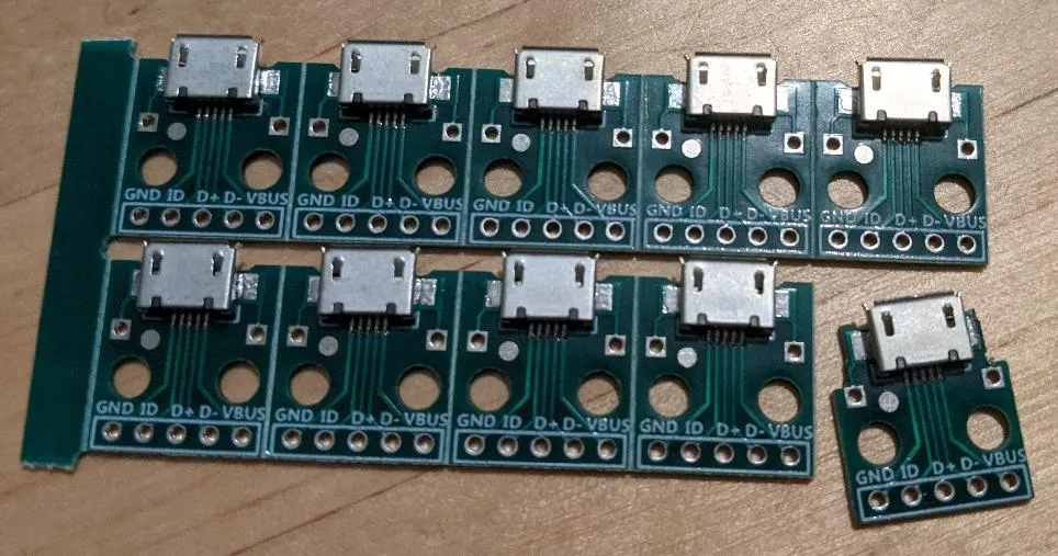
I bought some pre-built micro USB socket modules, and carefully dremeled the edges of one down so it would fit in the cable hole in the original base; the new socket was slightly too wide.
Then it was back to the measuring and Fusion 360 work to make a custom socket. I ended up with a piece pushed through from the outside, with a circular washer holding it from the inside.
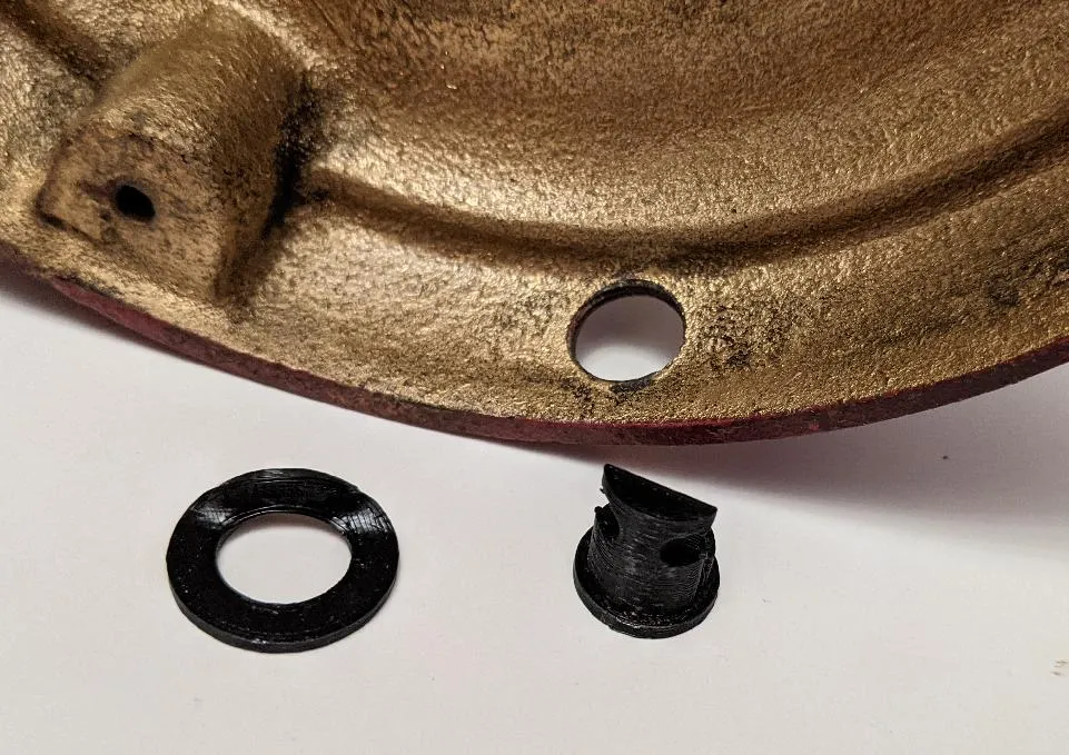
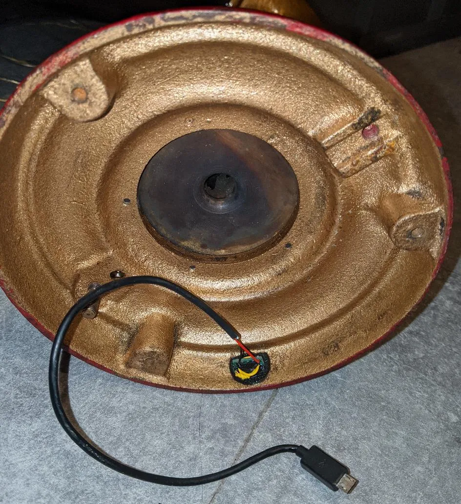
Both are then epoxied onto the base/together with two-part Araldite. The micro usb socket is then pushed into place and held in with a twist of wire.
Finally, I chopped a micro USB cable in half and soldered it onto the socket so it can provide power internally. Oh by the way - the opening in the middle of the base you can see on this picture is the opening for the audio to escape through the horn.
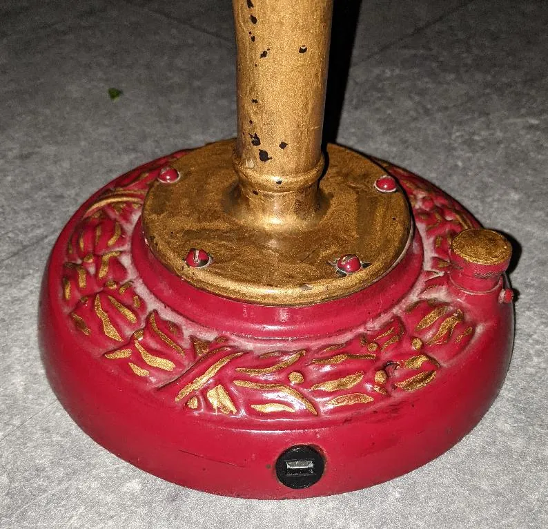
From the outside, it looks pretty cheeky :)
Design: Electronics
I had a Raspberry Pi Zero W hanging around in a box in the cupboard, so I used that as my base platform. I then acquired:
Wiring it together was pretty straightforward so I won’t go into much detail: the USB cable from the socket I made above just plugs into the Pi for power.
Putting it all together
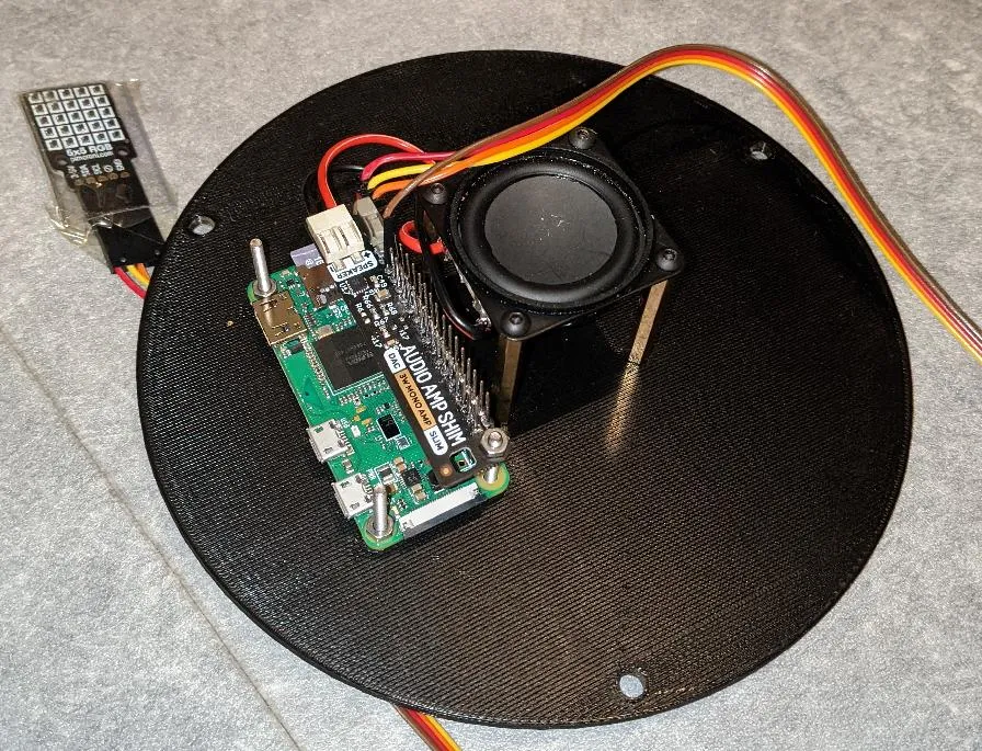
- The speaker is mounted centrally on some brass 35mm PCB standoffs to bring it next to the horn opening.
- The raspberry Pi/audio shim are mounted next to it on some small 3d printed plastic offsets.
- The 5x5 RGB Matrix is fed down through the horn itself and hangs out inside the horn tube (I encased it with some packing plastic from one of the tools I bought the other day to prevent short circuits).
- Finally, I can use the three feet from the original base to install it all!
Software
Pimoroni do a great job of after-sales support: The shop pages linked above contain lots of useful information, code examples, links to github etc.
I used mopidy as the playback software, linked it my Spotify account with the appropriate addon (mopidy-spotify): I can control the playback through its web interface!
Mopidy can also play local files really well, but Spotify is really quite convenient.
I’m not quite sure what to do with the 5x5 LED matrix: I’m just using it to create mood lighting from inside the horn at the moment.
Summary
So, its done. It looks great. Surprisingly, it actually sounds pretty good as well, although don’t expect a great bass response.
I’m finding it really convenient to play podcasts and background music on! Also, you can legitimately say “I need to ssh into the horn”: what’s not to like?
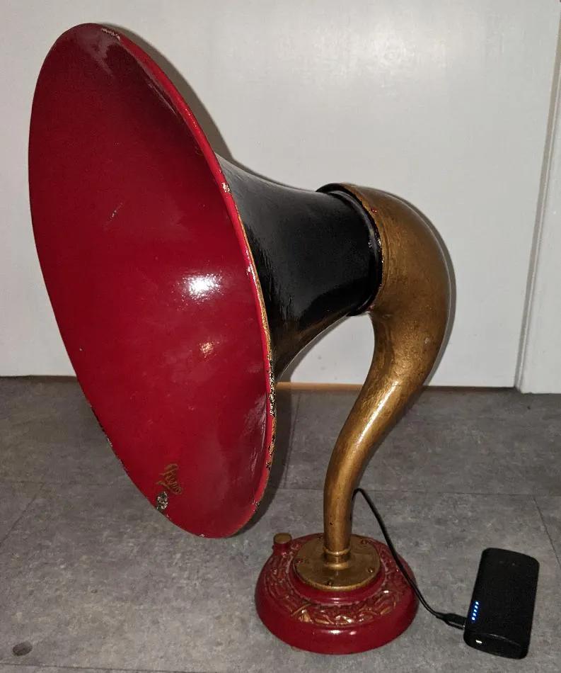
As you can see I can easily power it from a USB brick (its a Raspberry Pi after all!): a portable playback system to take down the park? Hah, maybe not :)
Leave a comment
Comments are moderated, so yours won't appear immediately. Your email is never published.