I quite fancied one of these AxiDraw drawing machines, but at the price they go for, I couldn’t really justify it.
However, I did some looking around and found this home-made version: I can definitely justify making one myself. I already had a Keyestudio CH340 Arduino Nano clone and Keyestudio CNC shield v4 in the cupboard from a project I never got round to doing. So I ordered the rest of the parts and set to making it one weekend.
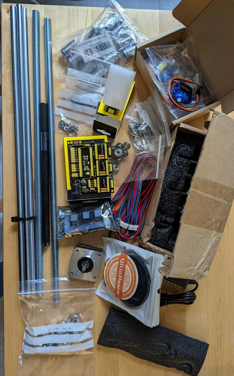
It went together pretty well:
I’ve posted the various parts mentioned throughout this post to various places:
- Replacement 3D printed parts are on Thingiverse.
- Updated GRBL with servo support is on Github.
- My 4xidraw svg to gcode is here on Github.
However, it was quickly obvious there were some big design issues:
Rods pop out the frame
Once I put it under tension, the rods immediately popped out of the frame.
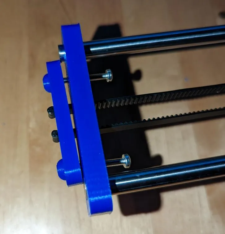
To fix this, I redesigned the “Yend” piece so it covered the rods preventing this:
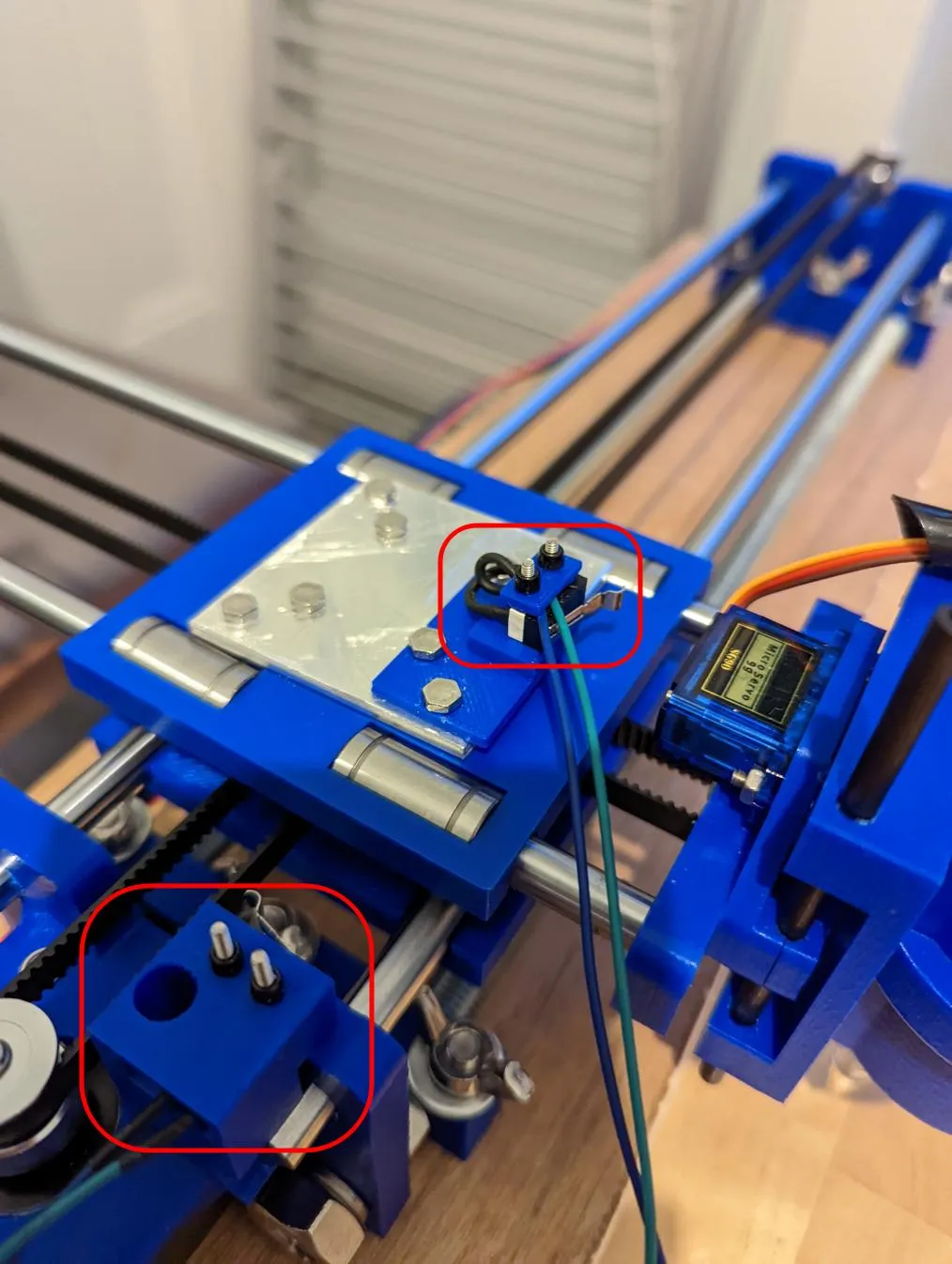
Lack of End Stops
There are no end stops in the machine. I always find this means it will immediately try and exceed one of its limits and start making distressing grinding noises.
I designed retrofitted plastic parts to hold some limit switches I had in the cupboard and installed them. I wired them into the X/Y axis limit headers on the CNC shield.
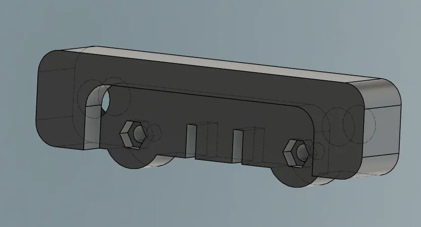
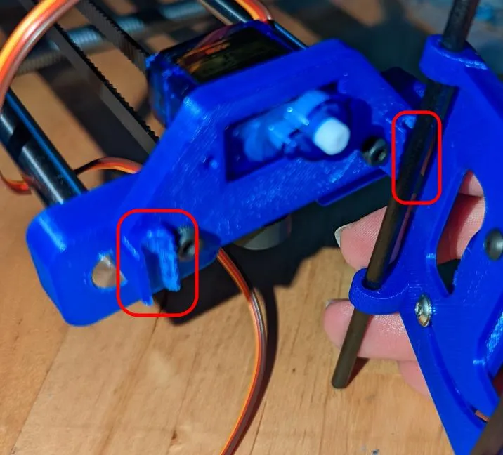
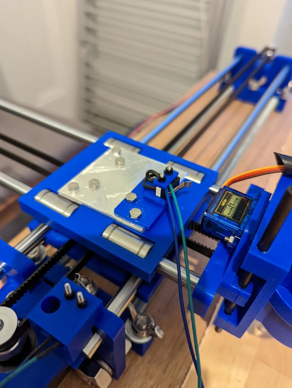
Weak Servo Holder
I had real difficulty attaching the carbon fibre rods to the servo holder: the retaining clips would pretty much immediately break the plastic holding them. So, I redesigned it to have proper detached clips; they’re tightened by the same bolts that attach the holder to the frame.
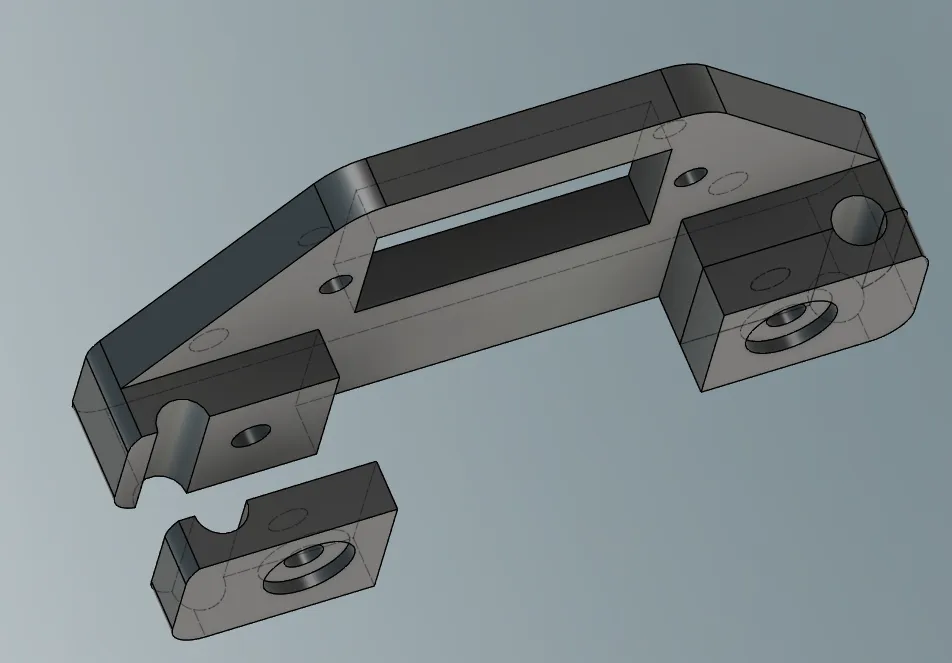
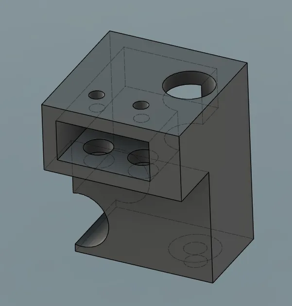
Flimsy Pen Carriage
The pen carriage was extremely flimsy: this caused the pen to wiggle about during drawing, causing the drawn lines to wiggle as well. I redesigned it to be much more sturdy. I also took the opportunity to add some recessed slots and holes to get at the servo holder bolts; it means its really easy to adjust the carbon rods.
Flimsy Pen Holder
Pretty much as soon as I tried to draw something, this happened. The pen holder doesn’t cope with any sort of stress:
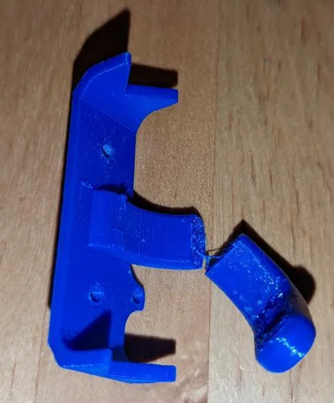
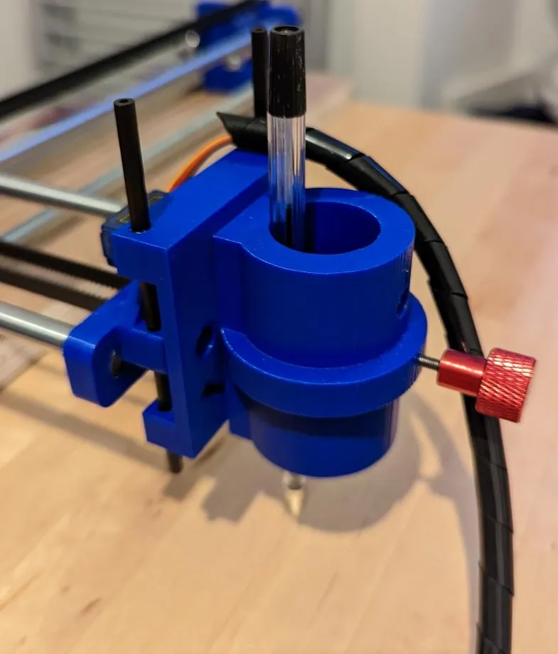
I redesigned it completely to be much more robust, and also to cope with larger pens. This also means its a bit heavier, helping the pen to make contact with the paper better:
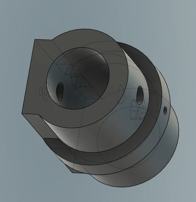
The complete redesigned pen assembly looks like this:
Device Wobbles During Drawing
Since the drawing arm extends so far, the entire device wobbles quite drastically during drawing: sometimes its actually supported by the pen itself.
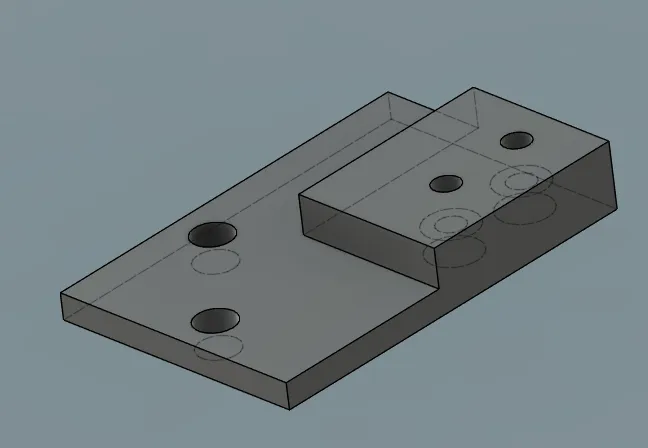
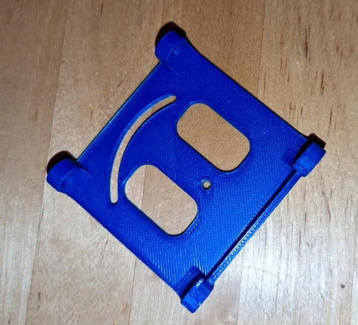
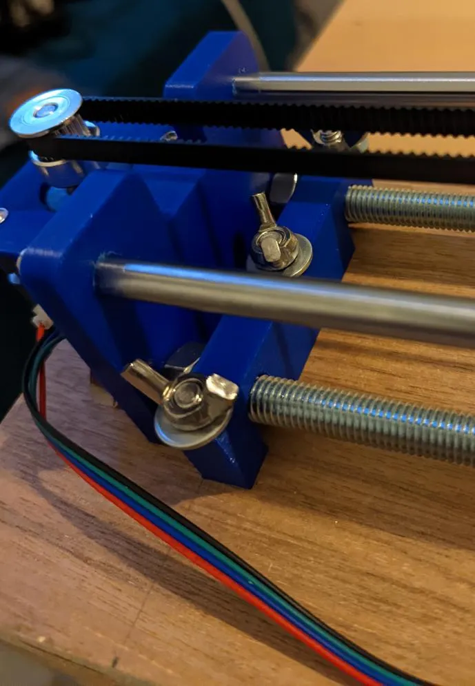
I designed some simple retaining parts to clip onto the threaded rods. I used a piece of 15mm thick plywood I had in the cupboard from refitting our kitchen floor, some 6mm recessed bolts and some butterfly nuts to attach the device to it.
There are two retaining parts at each end of the device. Below is one of them:
Threaded Rods Come Loose
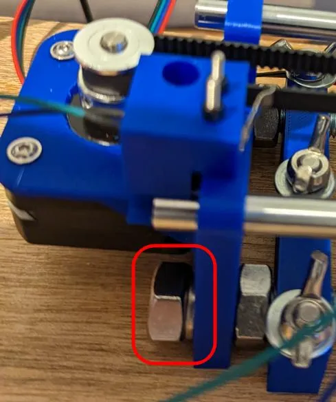
The nuts holding the threaded rods on the base quickly loosen due to vibration, so I added some split ring washers to prevent this.
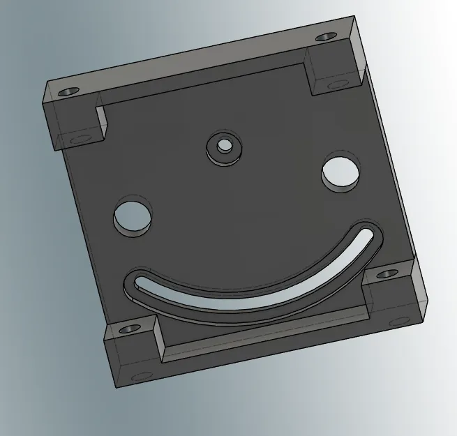
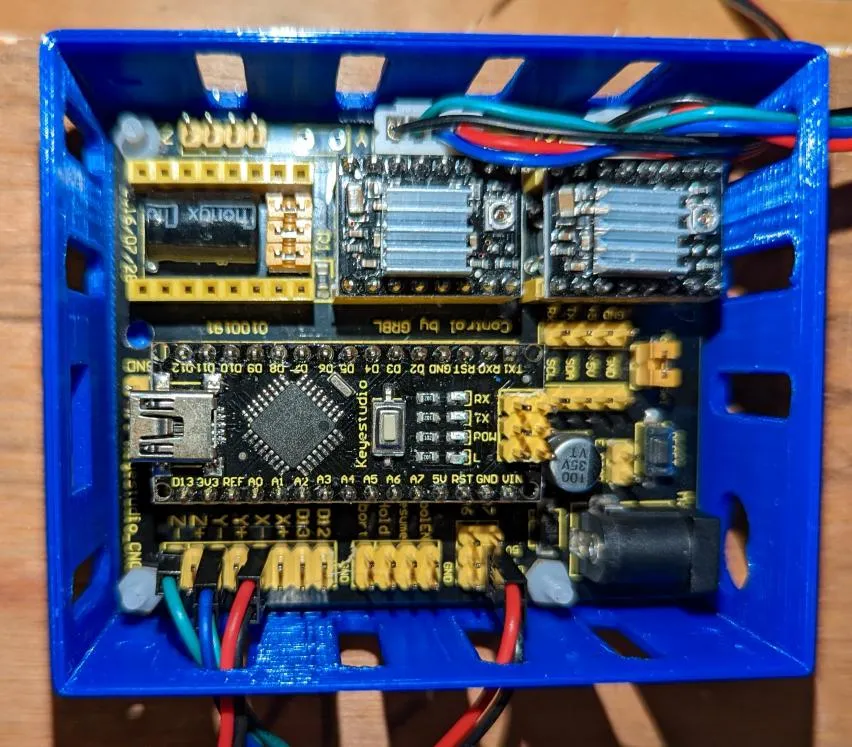
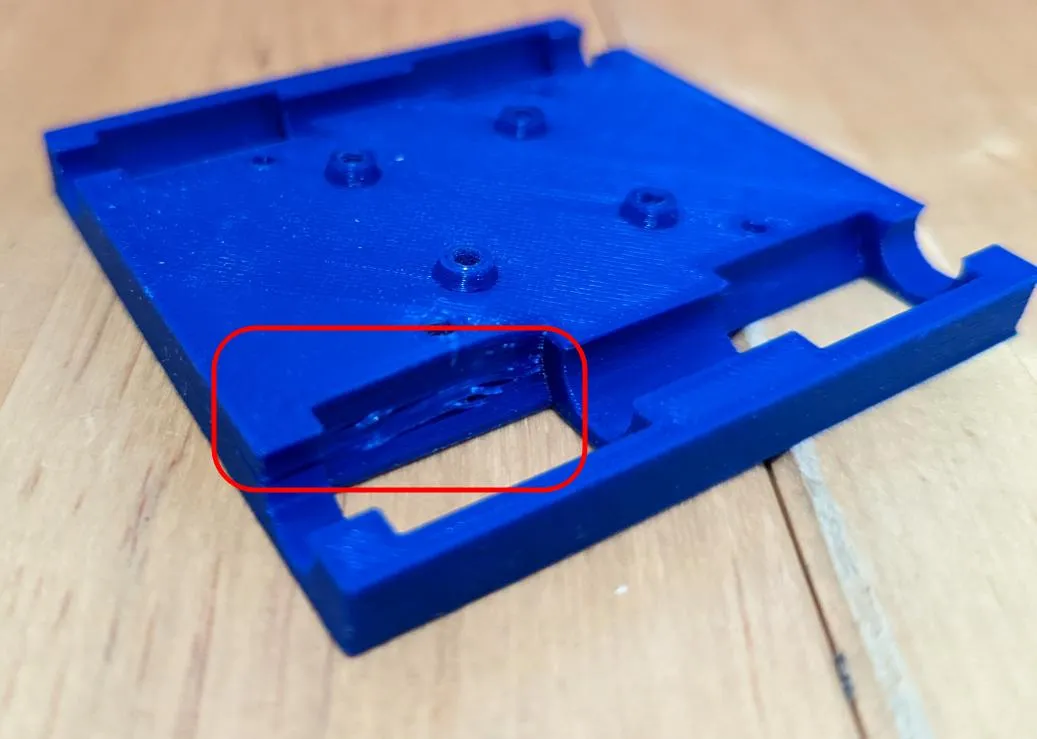
Box for Control Board
I didn’t like the way the original design held the control board (and it didn’t fit mine), so I found this design on thingiverse which fit it exactly. It looks pretty nifty!
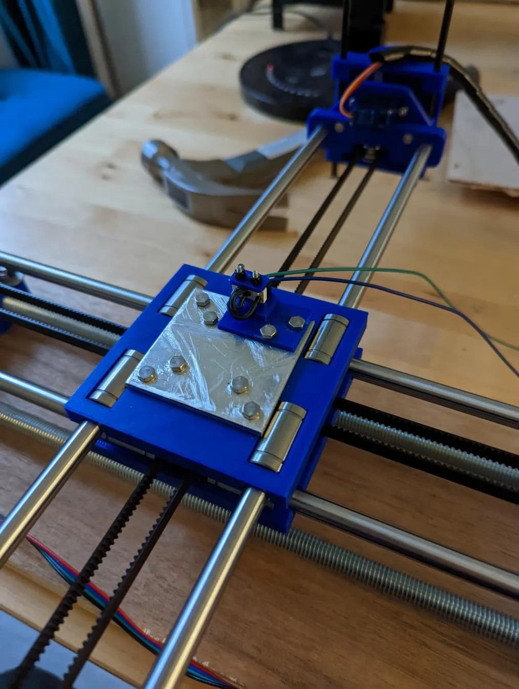
Crosspiece Wobbles/Breaks
The final big problem was the crosspiece where the two sets of rods meet. It was kinda wobbly. I tried tightening it up, but there was a cracking noise: the plastic had broken.
I reprinted the broken plastic piece. I thought how I could make it more sturdy: the big problem was the bolts/nuts put all the stress on the relatively weak plastic.
I ordered some 50mmx50mm 3mm aluminum plates and designed the same pattern of holes as on the plastic parts. I then used my desktop CNC to cut the holes into two of the aluminium plates.
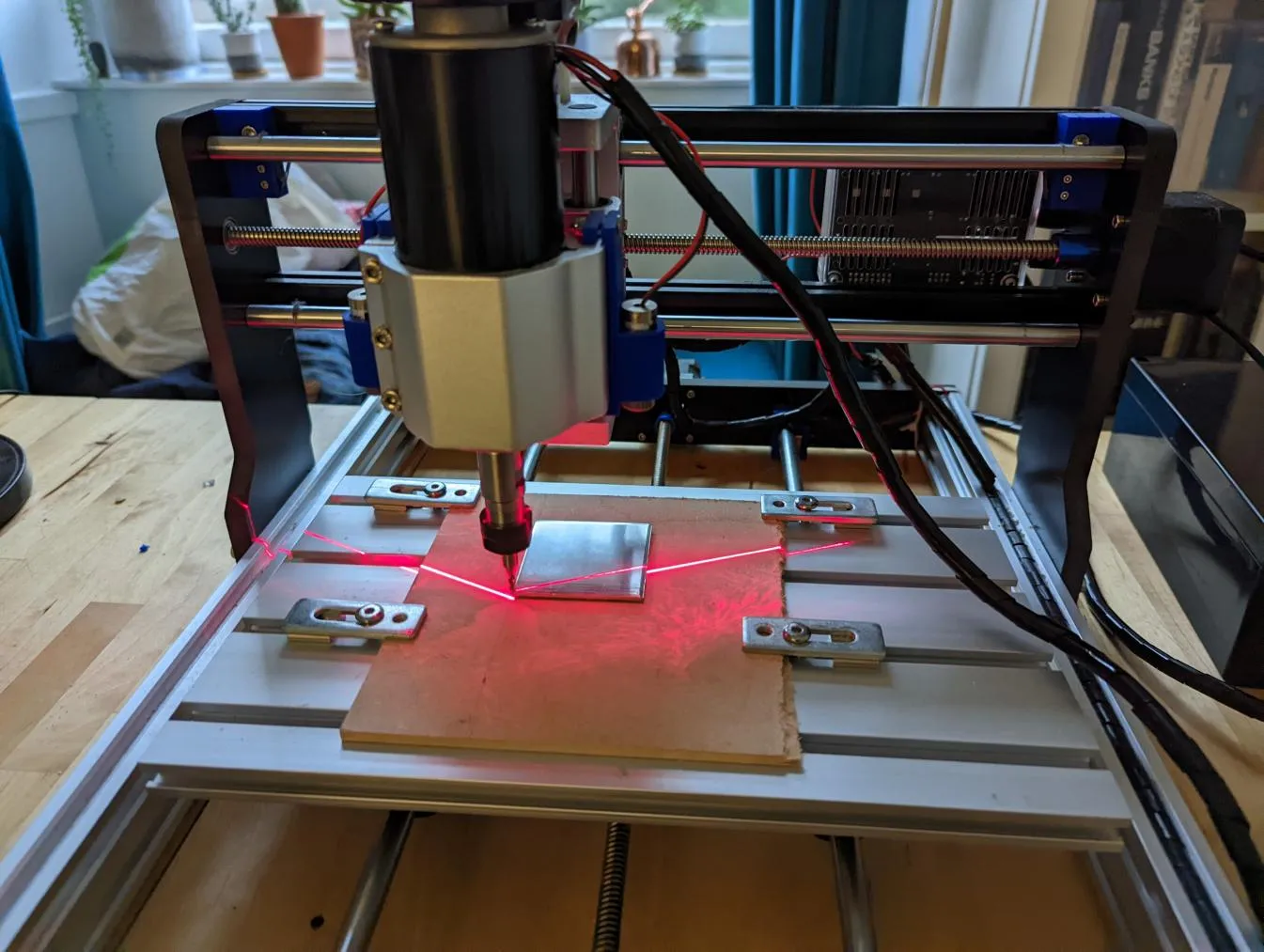
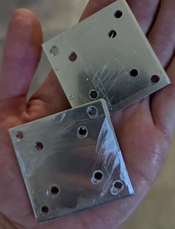
This was the first time I’d used the CNC to cut metal. I think its quite close to the edge of its abilities, but I managed to get it to do it by massively slowing down the rate it plunges down into the material. I didn’t have any proper drill bits so I had to use a flat end mill instead: the wrong tool but it did work mostly (and didn’t break the bit either). I’ve ordered some small drill bits for it for next time.
I attached a plate to the top and bottom of the crosspiece with some longer bolts and tightened it up without fear of the plastic breaking: this has pretty much eliminated the wobble.
Servo Wiring Problems
One issue is the CNC shield I’m using was clearly designed for a version of GRBL before they added variable spindle support (a modified version of this feature is used to control the servo motor, see later). In later versions, they realised they needed to shoogle the pinout slightly to enable this.
As a result, the pins labelled “Z endstop” on the board are actually used to control the spindle/servo. Not really a problem as you can plug whatever you want into them, but it is slightly confusing if you’re not aware of it.
GRBL Software Problem
The original instructions point to this git repo. This contains a slightly modified version which allows control of the servo motor.
The problem is its an ancient version of GRBL. I wasn’t happy with this so I have ported it to the latest version of the GRBL code, and made it available here. The changes for it are surprisingly small, but you do need them for the servo to function reliably. (It sort of works without them, but it isn’t good).
GRBL Compiler Problem
The next problem was as soon as I compiled and tried to upload it, I got errors about the size being too large: ie the compiled GRBL was too big for the flash on the Arduino.
This is was because I was using the latest version (11.2.0) of the AVR-GCC compiler on my laptop. However, since GRBL was coded, the compiler has been developed more, and now unfortunately builds binaries which are a bit larger than they used to be: too large for the tiny flash on the Arduino Nano clone.
I fiddled about trying to install older versions for a while, but I eventually settled on using PlatformIO. That project supports VS Code, and maintains a suite of compilers for each platform they support: for the Arduino Nano, they maintain the older compiler which generates smaller binaries.
GRBL Hard Configuration
Some configuration in GRBL can be done at runtime, however, some of it needs set during compilation (I assume this saves space for fundamental things you don’t generally want to change).
Since this device is a “HBOT”, it needs the “COREXY” support enabled to make it work properly. I did so by adjusting config.h.
Secondly, I needed to change the homing cycle to remove the Z axis: once again this is done in config.h.
The only other changes in grbl are the tweaks for servo control as mentioned earlier.
Bootloader Problem
Now I had GRBL compiled with all the features, it was time to upload it to the Arduino! You can do that from the PlatformIO GUI easily enough.
But now I was getting weird “verification” errors during flashing and the device didn’t boot. I eventually figured out that because this is a cheap clone device, its using an older, larger bootloader which is a “whopping” 2k in size. GRBL actually needs 1.5k of that space (hmmm, fighting over 1.5k of memory takes me back).
The verification errors are because the bootloader is “locked” to prevent you accidentally overwriting it: the last 1.5k of GRBL was trying to overwrite the bootloader, failing because it was locked, and then failing to verify.
There’s a solution for this: there is a newer bootloader, Optiboot, which only uses 0.5k, leaving the rest for GRBL, so I needed to upgrade to that.
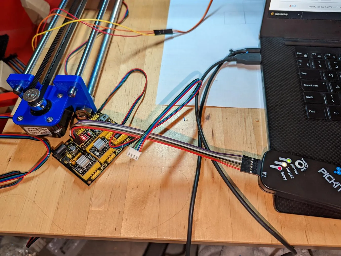
Guess what? Not so simple: you can’t update the bootloader from an existing bootloader, you need “special programming hardware” to do it using the avrdude flash programming software.
Hmm, special programming hardware? Just on the offchance, I checked and it does in fact support the Microchip PICKit2 (nearly everything does!). These devices were originally for programming Microchip PIC controllers, but actually its a versatile configurable hardware device. They’re also pretty cheap (well, the cheap clone ones from ebay are).
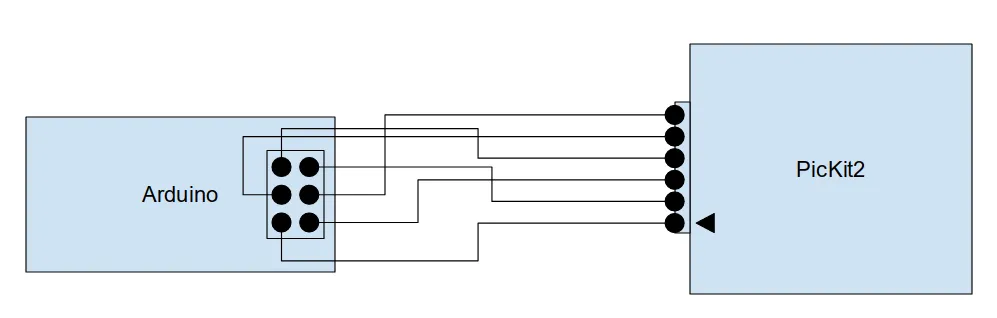
OK, so, next up, figure out how to wire the pickit to the arduino: there’s a six pin ICSP header for this purpose on it. You can find the ICSP pinout here, and the avrdude manual gives the Pickit2 side.
| arduino ICSP header | pickit |
| RST | 1 (Vpp/MCLR) |
| VDD | 2 (Vdd) |
| GND | 3 (GND) |
| MISO | 4 (PGD) |
| SCK | 5 (PDC) |
| MOSI | 6 (AUX) |
In case either of those links go missing, I’ve also drawn it up here:
To program the bootloader, clone the optiboot repo, then edit optiboot/bootloaders/optiboot/Makefile.isp and change the parameters to look like this
+ISPTOOL        ?= pickit2
+#ISPPORT       ?= /dev/tty.usbserial-FTD61T6Q
+#ISPSPEED ?= -b19200
Finally, run make atmega328_isp from the optiboot/bootloaders/optiboot folder and it will reprogram the bootloader! It reported a verification error for me “reading input file 2f”, but it seemed to work fine otherwise.
The device will reboot, and function exactly as before. Only now you can also fit the updated GRBL firmware onto it!
GRBL Soft Configuration
Once it was finally up and running, there are a couple of runtime parameters needing tweaked:
- You need to invert one of the X or Y axes: just a consequence of the HBOT configuration.
- Now we have endstops, you can enable the standard homing cycle and set soft limits.
- Due to where I had mounted my endstops, I needed to make it home in the opposite direction from GRBL standard.
- You need to set the steps per mm as per the original 4xidraw instructions.
Converting an SVG to GCODE
I tried using this software as recommended by the original instructions, but I found it a bit buggy and unmaintained.
Therefore, I found an alternative python library, svg-to-gcode, and put a small program together to drive it and add instructions control the pen holder. This reads an SVG file and generates a GCODE file to drive the machine on disk. The code for this is here.
One thing I did notice was that it kept missing small pieces of the drawing! I figured out I needed to add a small pause to allow the pen to descend to the paper before continuing drawing using the GCODE G4 command.
Sending the GCODE
You need to send the GCODE file to the device somehow: I did try writing something myself, but I ended up just using UGS Platform as usual: its great, has a comprehensible GUI, and is under active development. I’ve even contributed a workaround for a GUI glitch to the project previously.

Note: I spent some time getting very confused by the GRBL axis setup. Apparently - as per tradition - the (0,0) position is at the top right of the possible space: during homing, GRBL will establish and home to the (-maxx, -maxy) position.
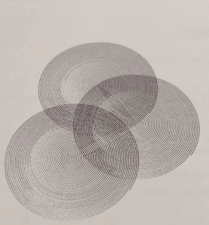
Results
This is actually my stress test to check the machine is reliable: three overlapping spirals. It’s drawn them pretty accurately! The ink fades in and out as I was using a cheap ballpoint pen, but I actually quite like the effect.
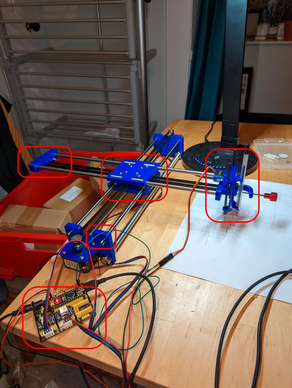
Here’s a picture of the complete, improved machine:
What Next?
I’d want to try out some algorithmically generated drawings, as well as some more conventional ones.
Since the pen holder is quite large, I’m thinking of making some replaceable cartridges so you can quickly and easily swap pens when doing a multi coloured drawing.
1 Comment
bullestock ·
You might want to take a look at the Inkscape plugin which I ported from the original Axidraw version: https://github.com/bullestock/4xidraw