Introduction
In our old flat, we had control over our heating from our phones: I’d reverse engineered the RF control protocol used by our Salus thermostat. I never got round to blogging about that, but the code is available here.
Now we’ve moved, we wanted the same control. The new boiler is a “Baxi 600” which had yet another RF controlled thermostat with yet another undocumented protocol (yawn!); I didn’t want to bother faffing with that this time. Instead, I decided to interface directly onto the boiler using the OpenTherm protocol.
OpenTherm is a two-wire low voltage electrical interface for controlling HVAC systems, as described on the OpenTherm website. Of course, you won’t find any useful details on there, because – besides the name – it’s only “open” if you’re in the happy throng of boiler/HVAC manufacturers.
However, if you search for “opentherm pdf” you’ll find a document describing the technical details of v2.2 of the protocol: good enough. It looks like we’ll be able to retrieve data from the boiler as well: moar charts, yum!
TL;DR? the code for this is here.
Implementation
Hardware
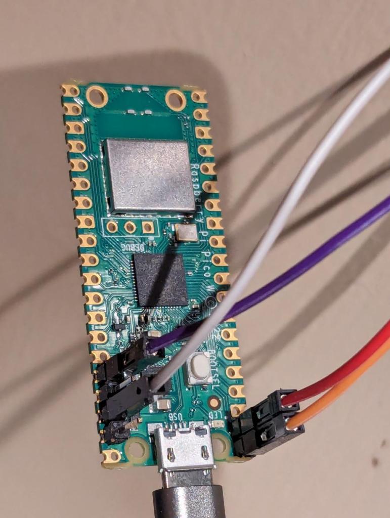
I wanted to use a Raspberry Pi Pico W again: I thought they were cool hardware, but had never had the excuse to use one. One of the really cool features is the PIO hardware, which lets you define a low level IO state machine rather than bit banging IO lines at the software level. The OpenTherm low level bit interface was an ideal fit for it.
Electrical Level
At an electrical level, Opentherm sends signals in one direction using voltage levels and in the other using current levels. I didn’t really want to get into that as it’s not really my thing.
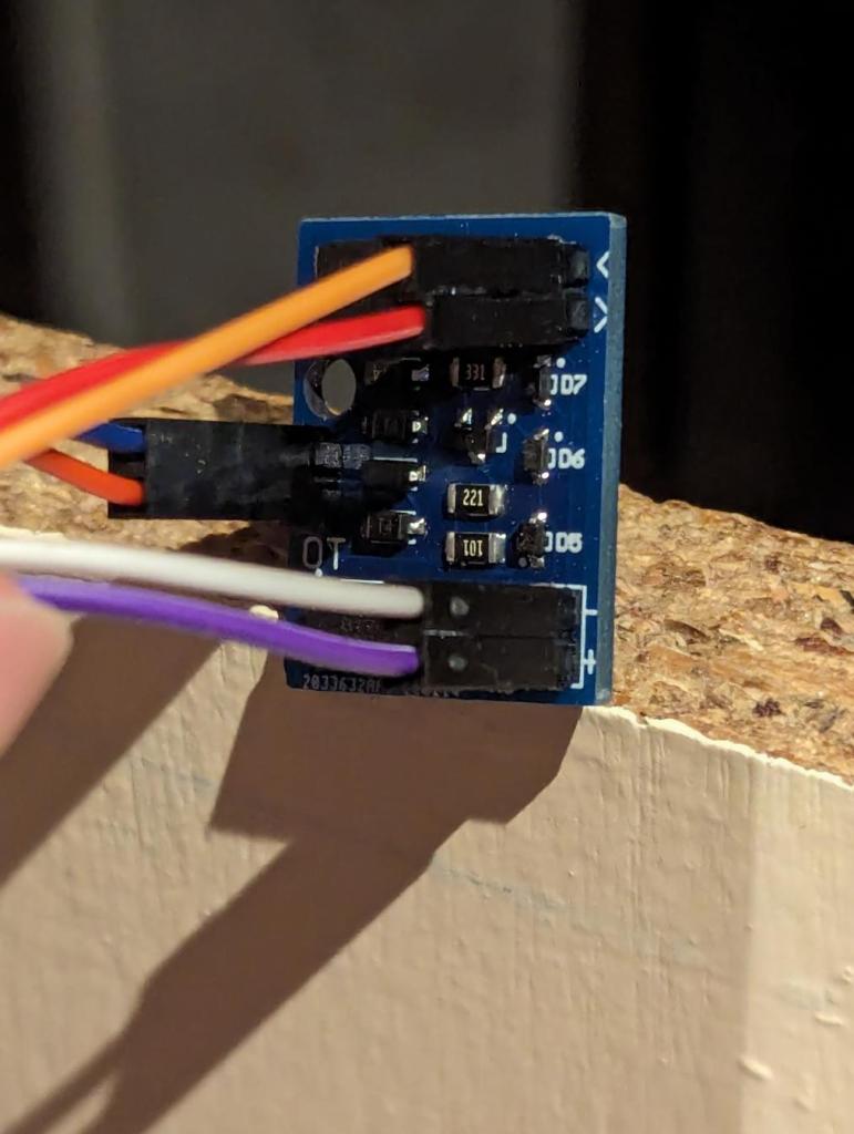
Searching around on the internet, I found this cheap Opentherm interface module for microprocessors made by Ihor Melnyk. I ordered it, and it arrived pretty quickly.
Ihor actually has his own Arduino library for OpenTherm, but I wanted to do it myself on a Pico (I really wanted to play with that PIO hardware!)
What is quite nice is this adapter is opto-isolated from the boiler.
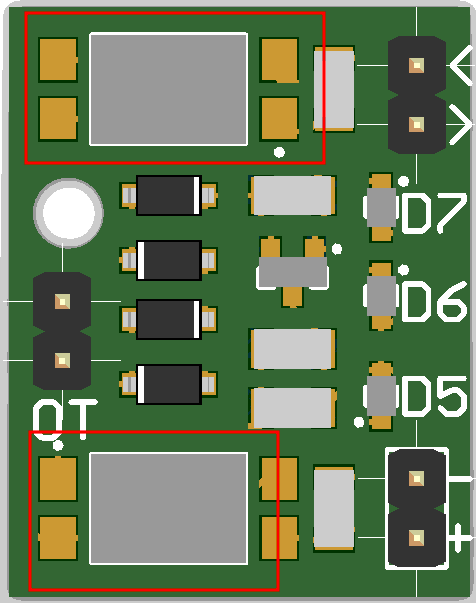
See those things I’ve drawn red rectangles around? They’re actually optoisolators. This means there is no electrical connection between the boiler and the Pi Pico whatsoever.
Low Level Protocol
OpenThem messages are always 32 bits of data, sent in little endian bit ordering. The controller (thermostat) sends a message, the controlled device (boiler) responds to it. The boiler cannot send a message of its own accord.
However, before being sent over the wire, the messages are encoded using Manchester encoding, avoiding the need for an extra clock signal to keep the two devices in sync. Since Manchester encoding sends two bits for every data bit, we actually send 64 manchester encoded bits over the wire.
I implemented the raspberry pi specific bits here, including the nifty PIO code for sending the raw data bits.
High Level Protocol
At the highest level, messages contain three key fields:
- Message Type – The direction of the message as well as whether it is reading, writing, or an error.
- Data Id – Which item of data is being transmitted (eg temperature, or water flow rate).
- Data Value – The value of that data item.
There are a whole load of pre-defined data-ids in the standard; I added basic implementations for all of them here. Later editions of the standard add more data ids supporting more exotic devices, but later versions of the documentation properly describing them have not been leaked, and I don’t need them for my boiler.
Finally, the main loop is here; it exposes the boiler over Wifi+MQTT for Home Assistant to access, as well as communicating with the boiler itself. Once again, I used python’s asyncio feature, and Thorsten von Eicken’s mqtt_async.py code to achieve this.
Debugging
Loopback debugging
First thing to check was that I’d got my code working at all: could I send and receive OK? I simply wired the Pico’s receive pin directly to the transmit pin and sent some messages to check I could decode what I sent. This seemed to work fine.
Connecting to the boiler
Next up, I had to connect the thing to the boiler:
- I had to install two-wire-pair into the boiler into its “low voltage control port” – this carries the OpenTherm protocol. Details on this were in the boiler’s manual.
- Secondly, I had to wire everything together; the pico, the opentherm adapter, and the boiler.
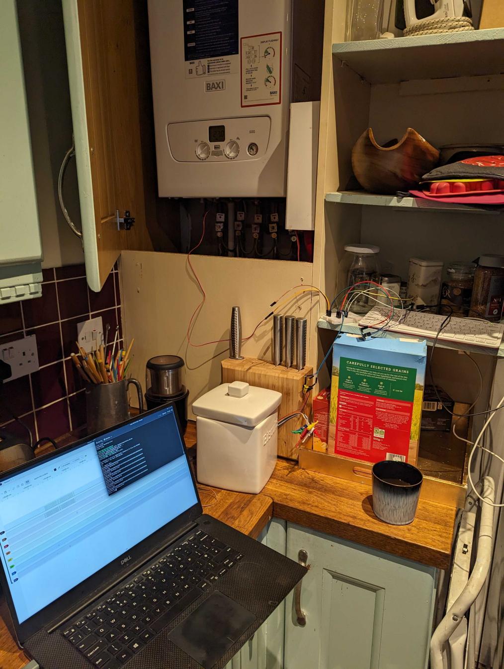
HOWEVER, I needed some way to watch and debug the Pico, it’s extremely unlikely it will be bug free. So, I dug out my Raspberry Pi 400 as well: I could remotely login to it and compile+upload new Pico firmware as I found issues and fixed them. I set up a small debugging station:
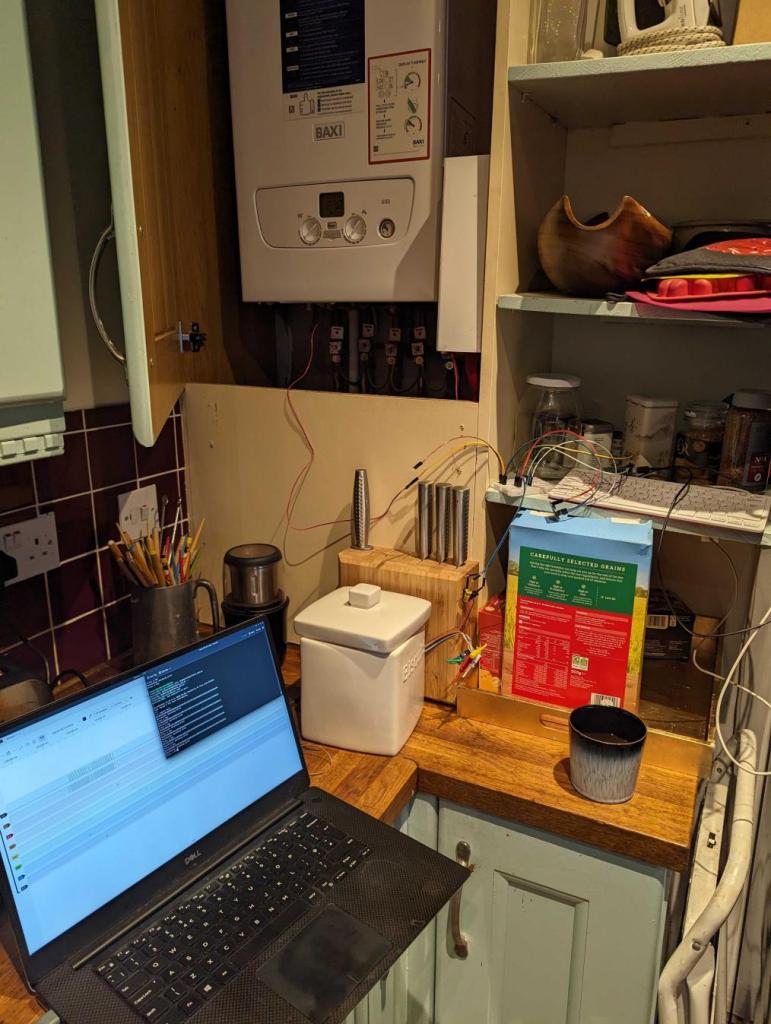
(Please ignore the paint colour/tiles/etc in the kitchen; it came with the house, we’re working on it!)
Electrical(-ish) level debugging
This is an epic…. Technically this is debugging the electrical level and the low level protocol level at the same time, but it’s kinda hard to separate the two of them.
My vain hope it would “all just magically work” proved unfounded, so let’s get going!
Debugging the Pico side
Since I had implemented the low level protocol myself, the first thing to check was the Manchester encoded bit pattern that was being sent out of the Pico. But how? I needed some sort of logic analyser hardware attached to the Pico‘s output/inputs.
My first attempt was using my “good ole” PICKit2. This is a device ostensibly for programming Microchip PIC microprocessors, but it’s actually a general purpose tool for a wide variety of purposes. The awesome open source signal analyser, sigrok, supports it, but I found it not to be suitable for my purpose here: its memory buffer simply wasn’t big enough to capture the entire bit pattern.
After some research, I bought this cheap logic analyser hardware, perfect for this. I set about sending and recording some signals.
The analyser has 8 channels, so it’s not a problem to capture the data sent from the Pico and also the reply from the boiler at the same time. However…
I can see the data being sent, but there’s nothing coming back from the boiler. Hmm…
OK, first thing: eyeball the bit pattern and decode it by hand. After a while, it turned out it had two problems:
- The bytes were in the wrong order
- The bits within those bytes were in the wrong order.
- Double-dimensionally-wrong-endian Batman!!
This was mainly because I’d wanted to see how well GitHub Copilot could cope so I’d asked it to write (or regurgitate?) that. And – apart from being wrong – it was some nice code, but to be fair to it, I hadn’t specified the bit ordering I wanted. Anyway, I fixed that aaaand… Nothing: It still didn’t work: Huh?
Oh low level protocol development: so much “fun” and head scratching!
Debugging the OpenTherm side
OpenTherm transmits data to the boiler using voltage levels, and receives data from the boiler using current levels. The hardware I’d bought deals with all that analogue stuff and converts it into nice bitstreams between 0->3.3v.
Unfortunately this means I couldn’t use my new logic analyser on the OpenTherm side, as it’s not a simple logic signal – its Weird Analogue Shit™.
If I had an oscilloscope I could probably use that, but I don’t. So I used my trusty multimeter to check the voltages when I sent a 1 vs sending a 0: The OpenTherm voltage was Not Quite Right.
Somehow (and I cannot remember how now; I suspect this is just down to years of experience fiddling with this sorta stuff), I realised that I needed to invert the bits sent to the OpenTherm adapter:
- I’d assumed that the base level of the Pico output should be a 0 bit.
- But on the OpenTherm side, it actually needed to send a 1 bit to the boiler constantly. Doing this means the voltage on the line is changed from its nominial value by the OpenTherm adapter.
- The boiler then spots this changed voltage and so knows that an OpenTherm controller is attached!
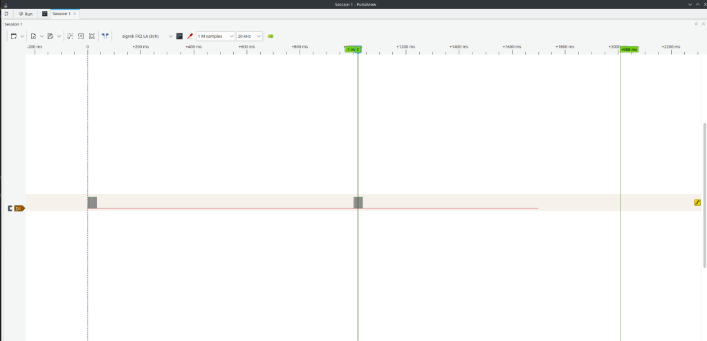
I made the changes to invert the transmitted bits, sent a test message, and watched the results in the signal analyser:
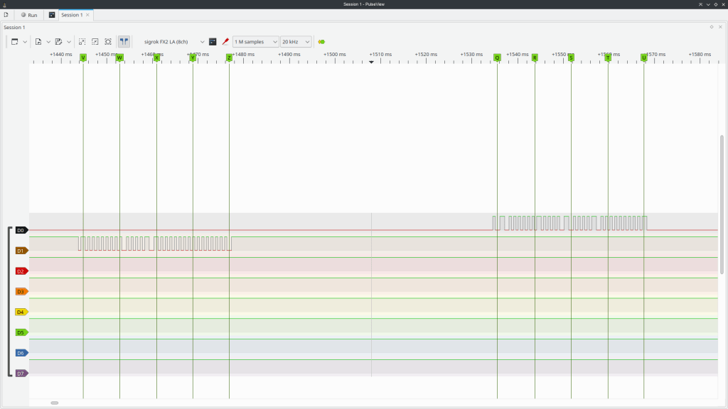
YAY! The boiler replied: it’s talking to me! (Note the bits in the leftmost – first – message are inverted, but those in the rightmost are not!)
Shortly afterwards, the boiler went into a weird mode and showed an error code on its display: OH CRAP!
Application level debugging
So, mildly panicked, I turned the boiler off and on again. Once more it came up with an error code. AAARGH! I started thinking of how one might explain this to a boiler maintenance person.. “Erm, the boiler has mysteriously started being… weird?”
I tried a few more times, and then sent another OpenTherm test messsage. The error code vanished, and the boiler came back to life!
It turns out, in the OpenTherm protocol:
- If you indicate a controller is attached by changing the line voltage by pulling it high with a 1.
- Then you need to communicate with the boiler every few seconds or it will assume it has lost connection to the controller and enter a failsafe shutdown mode until it comes back.
- So basically, if you aren’t pinging the boiler every few seconds, you need to turn off the Pico first, so the line voltage returns to normal.
- The boiler will then return to its default control mode (on its front panel).
- Phew!
Anyway, debugging the application level was basically just a matter of figuring out what OpenTherm features the boiler actually supports and coding them up. As it turns out, this is quite limited: you can set the hot water + heating target temperatures, as well as enabling/disabling the hot water and heating. That’s about it.
The thing that took the longest was publishing the metadata so that Home Assistant was able to auto-detect the boiler and expose it on its GUI.
HOWEVER, you can read all sorts of lovely monitoring data out of the boiler…
Monitoring
Once everything was working I simply removed the Pi 400 and just let the Pico + OpenTherm adapter hang out in the boiler cupboard by themselves.

(the usb cable is purely for power)
Oh, for future-me, here are some pics of the wiring:
I then built this fancy dashboard on home assistant to monitor the boiler:
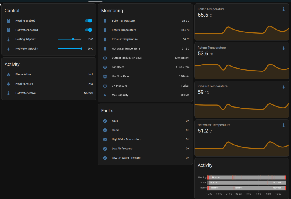
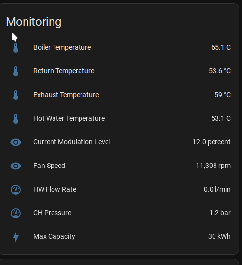
The target boiler temp is 65C, but we can see from the telemetry we’re losing about 12C in return temp from heating the house.
It’s a 30kW boiler, but it’s only actually needing to run at 12% modulation (30 * 0.12 = 3.6kW) – I’m hoping that’s because the condensing heat recovery has kicked in. Return temp of ~55 degrees is around right for that supposedly.
Although this is cool and all, the only actual button we tend to use is to turn the heating on or off 😀
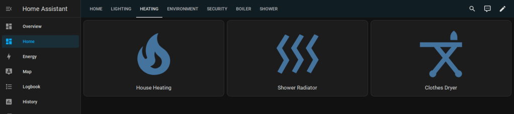
However, since HASS is exposed via a Wireguard VPN, we can now do that from anywhere in the world!
Summary
PIO
I really liked the PIO engine; it’s really very cool, saving a lot of bitbanging.
Slightly less good is its python incarnation; you can see the code here. The main problem I found was that it doesn’t sanity check the code properly. For example set(pins, 0). Other opcodes use a parameter of pin, and it’s really quite easy to miss off that S. The python code does not detect or report if you use the wrong one, so it generates the wrong PIO program! However, once you get through that and check everything, it works fine.
Github CoPilot
I used github copilot to write the unit tests and the manchester encoder as an experiment:
- Unit tests: great timesaver, but it doesn’t always get it right.
- Manchester encoder: as discussed, the code was good, but the byte/bit ordering was wrong.
I’ve been using it since this project: it’s very useful, but needs care and attention. I actually can’t face writing unit tests without it now!
Future
I had thought about capturing the data and using it to automatically control the boiler, but it doesn’t really seem worth it: a simple timer to go on in the morning does pretty much everything we need.
When I told my friends I was doing this, several of them gave me “a look”; I think they were expecting some sort of nuclear level event to be visible across the Edinburgh skyline. This hasn’t happened. Yet.
The thing occasionally (say once a month) crashes, requiring a power cycle. I don’t have the Pi 400 connected any more so I can’t immediately debug it, and generally we notice when we’re really f’ing cold and want the heating on ASAP: I’ve not got round to diagnosing this properly yet.
Update: I’ve just found that my core house control system, housebot, was running on Wifi rather than Ethernet (an AP just fell over and it started being really glitchy); fixed now. Hopefully this is responsible for the instability…
